Resistor sets the stage for understanding electrical circuits. They control current flow and are crucial components in various applications. This exploration delves into resistor types, characteristics, and practical applications.
From fixed carbon to more complex designs, resistors exhibit diverse properties. We’ll examine their roles in voltage dividers, circuits, and more. Understanding resistor color codes, power handling, and tolerance is essential for accurate circuit design and analysis.
Resistor Fundamentals
Resistors are fundamental passive components in electrical circuits, controlling the flow of current. Their primary function is to oppose the flow of electrons, converting electrical energy into heat. This opposition, measured in ohms, is crucial for regulating voltage and current within a circuit. Understanding resistor characteristics is essential for designing and analyzing various electronic systems.
Resistor Function in Circuits
Resistors are essential for controlling current and voltage in electrical circuits. They regulate the flow of electrons, limiting the current that passes through a particular branch of the circuit. This controlled current flow is vital for protecting components, ensuring proper operation of devices, and shaping the overall circuit’s behavior. By strategically placing resistors in circuits, engineers can achieve specific voltage drops across different components.
Resistor Types
Resistors are categorized into various types based on their construction and characteristics. Fixed resistors provide a constant resistance value, while variable resistors offer adjustable resistance.
Fixed Resistor Types and Characteristics
Fixed resistors maintain a constant resistance value. Different types exhibit varying characteristics in terms of tolerance, power rating, and temperature coefficient. These characteristics influence their suitability for different applications.
Variable Resistor Types and Characteristics
Variable resistors, also known as potentiometers, offer adjustable resistance values. These are commonly used for controlling the gain of amplifiers or for adjusting the brightness of a light. They consist of a resistive element with a sliding contact, allowing for continuous adjustment of resistance.
Resistor Parameter Specification
Several key parameters are used to specify resistors, allowing for accurate selection and use in circuits. Resistance, tolerance, and power rating are crucial factors.
Resistance
Resistance, measured in ohms (Ω), quantifies a resistor’s opposition to current flow. Higher resistance values limit current more effectively.
Tolerance
Tolerance indicates the acceptable deviation from the nominal resistance value. A tighter tolerance implies a more precise resistor.
Power Rating
The power rating defines the maximum power a resistor can dissipate without damage. Exceeding this rating can lead to overheating and failure.
Comparison of Resistor Types
| Resistor Type | Resistance Range | Tolerance | Power Rating |
|---|---|---|---|
| Fixed Carbon | A few ohms to several megohms | ±5%, ±10% | Fractions of a watt to a few watts |
| Metal Film | A few ohms to several megohms | ±1%, ±2% | A few watts to tens of watts |
| Wirewound | A few ohms to thousands of ohms | ±1%, ±2% | Tens of watts to hundreds of watts |
| Cermet | A few ohms to several megohms | ±1%, ±2% | Fractions of a watt to a few watts |
| Potentiometer (Variable) | Adjustable over a range | Dependent on type | Depends on the specific application and size |
Resistor Applications
Resistors are fundamental components in electronic circuits, playing a crucial role in shaping current flow and voltage levels. Their diverse applications span a wide range of electronic devices, from simple circuits to complex systems. Understanding their function in various contexts is essential for effective circuit design and analysis.Resistors are indispensable in controlling current flow and establishing specific voltage drops across components within a circuit.
This control is vital for ensuring the proper operation of other circuit elements and preventing damage to the system. Their ability to precisely define current paths and voltage levels makes them an essential element in diverse applications.
Resistors, crucial components in electronics, often need protection from environmental factors like dust. Finding affordable dust-proof enclosures for these components is important for reliable performance, especially in harsh conditions. Solutions like affordable dust proof housings can significantly enhance the longevity and operational efficiency of your resistors in the long run. Proper protection ultimately translates to less downtime and fewer replacements.
Voltage Divider Circuits
Resistors are frequently used in voltage divider circuits, which produce a desired output voltage from a higher input voltage. This application leverages the principle of voltage division, where the output voltage is a fraction of the input voltage. The precise output voltage is determined by the ratio of the resistances in the divider network. This method is crucial for powering different components with appropriate voltage levels.
Current Limiting
Resistors are critical in limiting current flow in circuits. Overcurrent can lead to component damage or malfunction. By strategically placing resistors in series with components, the current passing through them is controlled and maintained within safe operating parameters. This is particularly important for protecting sensitive components from excessive current surges.
Signal Conditioning
Resistors are used in signal conditioning circuits to modify input signals before they are processed further. This can involve adjusting the amplitude, filtering out unwanted noise, or converting a signal to a suitable form for subsequent operations. These circuits are crucial in various applications, including audio amplifiers, data acquisition systems, and sensor interfaces.
Temperature Sensing
Thermistors, which are temperature-sensitive resistors, are a prime example of resistors used in temperature sensing applications. The resistance of a thermistor changes proportionally with temperature, allowing for the measurement of temperature variations. These devices are commonly employed in climate control systems, ovens, and other temperature-sensitive equipment.
Table of Resistor Applications
| Application | Resistor Value (Ω) | Purpose | Circuit Diagram |
|---|---|---|---|
| Voltage Divider | 1 kΩ, 10 kΩ | Reduce input voltage to a specific level for other components | A simple circuit with a voltage source connected to two resistors in series. The junction between the resistors provides the output voltage. |
| Current Limiting | 10 Ω, 100 Ω | Prevent excessive current flow through a component | A resistor placed in series with a component, such as an LED, to limit the current. |
| Signal Conditioning | 100 kΩ, 1 MΩ | Adjust the amplitude and filter noise from an input signal | A resistor used as a part of a circuit to condition an input signal before it is processed further. |
| Temperature Sensing | (Variable, dependent on thermistor type) | Measure temperature changes by monitoring resistance variations | A thermistor connected to a circuit that measures the resistance change in response to temperature changes. |
Simple Circuit Design
A simple circuit employing a resistor, a LED, and a power source can illustrate resistor functionality. A 100 Ω resistor is placed in series with a 5 mm LED. The power source is appropriately rated for the LED and the circuit. This configuration limits the current through the LED, preventing damage and ensuring proper operation.
Resistor Color Coding

Resistor color coding is a standardized system used to identify the resistance value and tolerance of a resistor visually. This method is crucial for quickly and accurately determining the resistor’s specifications without needing to measure it. Understanding this system is essential for anyone working with electronic components.Resistor color codes consist of bands of different colors painted onto the resistor’s body.
These bands, arranged in a specific order, represent numerical values and tolerances. The order of the bands is critical for correct interpretation.
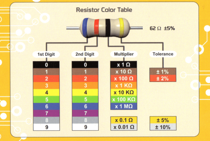
Resistor Color Code System
The resistor color code system uses a set of colored bands to represent the resistor’s resistance value. Each color corresponds to a specific numerical value. The first two bands represent the significant digits of the resistance value, the third band represents the multiplier, and the fourth band (if present) indicates the tolerance.
Reading Resistor Values from Color Bands
To read a resistor’s value from its color bands, follow these steps:
- Identify the first two bands. These represent the first two significant digits of the resistance value.
- Identify the third band. This band represents the multiplier, indicating the number of zeros to append to the first two digits.
- If a fourth band is present, it indicates the tolerance of the resistor. Tolerance represents the acceptable deviation from the specified resistance value.
Resistor Color Code Table
The table below illustrates the color code for various resistor values:
| Color | Value | Example |
|---|---|---|
| Black | 0 | A black band represents the digit zero. |
| Brown | 1 | A brown band represents the digit one. |
| Red | 2 | A red band represents the digit two. |
| Orange | 3 | An orange band represents the digit three. |
| Yellow | 4 | A yellow band represents the digit four. |
| Green | 5 | A green band represents the digit five. |
| Blue | 6 | A blue band represents the digit six. |
| Violet | 7 | A violet band represents the digit seven. |
| Gray | 8 | A gray band represents the digit eight. |
| White | 9 | A white band represents the digit nine. |
| Gold | 0.1 | A gold band represents a multiplier of 0.1. |
| Silver | 0.01 | A silver band represents a multiplier of 0.01. |
| No band | No multiplier | No fourth band means the multiplier is 1. |
| Brown | 1% | A brown fourth band signifies a 1% tolerance. |
| Red | 2% | A red fourth band signifies a 2% tolerance. |
| Gold | 5% | A gold fourth band signifies a 5% tolerance. |
| Silver | 10% | A silver fourth band signifies a 10% tolerance. |
Examples of Resistor Color Code Values
A resistor with bands colored brown, black, orange, and gold would have a resistance of 10,000 ohms with a tolerance of 5%. A resistor with bands colored green, blue, red, and silver would have a resistance of 5,620 ohms with a tolerance of 10%.
Resistor Power Handling
Resistors, despite their seemingly simple construction, play a crucial role in circuit design. A critical aspect often overlooked is their power handling capacity. Understanding and adhering to this limit is vital for preventing resistor failure and ensuring circuit reliability. Selecting a resistor with an appropriate power rating is paramount for safe and efficient operation.
Importance of Power Rating
The power rating of a resistor dictates the maximum amount of power it can safely dissipate without suffering damage or failure. Choosing a resistor with an insufficient power rating can lead to overheating, potentially causing the resistor to fail, open, or short circuit. This can disrupt the entire circuit’s operation and compromise the safety of the system. A properly rated resistor, on the other hand, ensures stable and reliable performance within the expected operating conditions.
Factors Influencing Resistor Power Dissipation
Several factors influence the power dissipation of a resistor. These factors include the resistor’s physical size and construction materials. Larger resistors, typically made of materials with higher thermal conductivity, can dissipate more power without overheating. The surrounding environment also plays a role. A resistor mounted in a well-ventilated area will experience less heat buildup compared to one in a confined space.
Additionally, the amount of current flowing through the resistor, and consequently the voltage drop across it, directly affects the power dissipation.
Calculating Power Dissipated by a Resistor
The power dissipated by a resistor can be calculated using the following formula:
P = I2R = V 2/R
where:
- P represents the power dissipated in watts (W).
- I represents the current flowing through the resistor in amperes (A).
- R represents the resistance of the resistor in ohms (Ω).
- V represents the voltage across the resistor in volts (V).
This formula allows for straightforward calculation of the power handling capacity based on known values of current, resistance, or voltage. Using this formula, engineers can readily determine if a resistor can handle the expected power load in a given circuit.
Examples of Exceeding Power Rating
Exceeding the power rating of a resistor can result in several undesirable consequences. One common outcome is the resistor’s failure, manifested as an open circuit, or in extreme cases, a short circuit. This can disrupt the circuit’s intended operation, leading to unexpected behavior or malfunction. Another potential consequence is overheating. The resistor’s casing may become excessively hot, potentially damaging nearby components or even posing a fire hazard.
This is particularly crucial in high-current applications, such as those found in power supplies or motor control circuits. For instance, in a high-power audio amplifier circuit, a resistor with insufficient power rating may overheat and fail, causing audio distortion or system shutdown. This is a clear example of the importance of selecting a resistor with an appropriate power rating for the specific application.
Resistor Tolerance
Resistors, crucial components in electronic circuits, are not perfectly precise. Their resistance values, while specified by a nominal value, can deviate from this ideal. This inherent variability is known as tolerance. Understanding tolerance is essential for predicting circuit performance and ensuring reliable operation.Tolerance, expressed as a percentage, indicates the acceptable range within which a resistor’s actual resistance can vary from its marked value.
A 5% tolerance resistor, for example, can have its resistance deviate from the marked value by up to 5%. This deviation can significantly impact circuit performance, particularly in critical applications.
Impact of Tolerance on Circuit Performance
Tolerance directly affects circuit accuracy. A circuit’s designed performance relies on precise component values. If the actual resistance of a resistor differs substantially from its nominal value, the circuit’s output may deviate from the expected behavior. For example, in a voltage divider circuit, variations in resistor values can lead to an output voltage that differs from the intended value.
This difference might be negligible in some cases, but in applications requiring high precision, even small deviations can be problematic.
Impact of Tolerance on Circuit Accuracy
The accuracy of a circuit is directly linked to the precision of its components. Higher tolerance values correspond to a wider range of possible resistance values, thus reducing circuit accuracy. For instance, a circuit requiring high accuracy, such as in a precision amplifier, would benefit from resistors with lower tolerances.
Resistor Tolerance Levels
Understanding the tolerance levels available for various resistor types is crucial for selecting the right component for a specific application. Different resistor types have different tolerances, impacting the precision they offer.
| Resistor Type | Tolerance (%) | Accuracy |
|---|---|---|
| Carbon Composition | ±20% | Low |
| Carbon Film | ±5%, ±10% | Moderate |
| Metal Film | ±1%, ±2% | High |
| Thick Film | ±0.5%, ±1% | Very High |
| Wirewound | ±0.1%, ±0.5% | Excellent |
Resistor tolerance, a critical aspect of circuit design, must be considered alongside other factors like operating temperature and environmental conditions. The choice of tolerance directly influences the accuracy and reliability of a circuit.
Resistor Types
Resistors, fundamental components in electronic circuits, come in diverse forms, each with unique characteristics tailored for specific applications. Understanding these types is crucial for selecting the right resistor for a given task. Their variations in construction and materials affect their performance, cost, and reliability.
Carbon Composition Resistors
These resistors utilize a mixture of carbon and other materials pressed into a cylindrical form. Their cost-effectiveness makes them suitable for many applications.
- Advantages: Low cost, readily available, and simple construction. Suitable for general-purpose applications where precision is not critical.
- Disadvantages: Lower precision and tolerance compared to other types, sensitivity to temperature changes, and relatively low power handling capacity.
- Applications: Commonly used in hobbyist projects, educational settings, and simple circuits where accuracy is not paramount.
Carbon Film Resistors
These resistors utilize a thin film of carbon deposited onto an insulating substrate. They offer improved precision and stability compared to carbon composition resistors.
- Advantages: Higher precision and tolerance than carbon composition resistors, better temperature stability, and moderate power handling capacity.
- Disadvantages: Still less precise and stable than other types, such as metal film resistors, and potentially more expensive than carbon composition resistors.
- Applications: Found in applications needing slightly higher precision than carbon composition, such as general-purpose circuits and instrumentation.
Metal Film Resistors
Metal film resistors utilize a thin metallic film deposited on a ceramic substrate. This construction results in higher precision and stability.
- Advantages: High precision and tolerance, excellent temperature stability, and good power handling capacity.
- Disadvantages: Generally more expensive than carbon composition or carbon film resistors.
- Applications: Used in applications requiring high accuracy and stability, including precision circuits, instrumentation, and telecommunications.
Wirewound Resistors
These resistors use a coil of resistive wire wound around a core. Their high power handling capacity makes them ideal for applications requiring significant power dissipation.
- Advantages: High power handling capacity, excellent stability, and low temperature coefficient.
- Disadvantages: Larger size compared to other types, potentially higher cost, and not as precise as other types.
- Applications: Common in high-power applications, such as power supplies, heating elements, and high-current circuits.
Surface Mount Resistors (SMDs)
These resistors are designed for surface mounting on printed circuit boards (PCBs). Their small size is advantageous for space-constrained applications.
- Advantages: Small size, high density packing on PCBs, and ease of automated assembly.
- Disadvantages: Limited power handling capacity, and may be more challenging to solder by hand compared to through-hole resistors.
- Applications: Widely used in modern electronic devices, including smartphones, computers, and consumer electronics, due to space constraints and automated assembly.
Summary Table of Resistor Types
| Resistor Type | Advantages | Disadvantages | Applications |
|---|---|---|---|
| Carbon Composition | Low cost, readily available | Lower precision, sensitivity to temperature | Hobbyist projects, simple circuits |
| Carbon Film | Higher precision than carbon composition | Lower precision than metal film | General-purpose circuits, instrumentation |
| Metal Film | High precision, excellent stability | More expensive | Precision circuits, instrumentation |
| Wirewound | High power handling capacity | Larger size | High-power applications |
| SMDs | Small size, high density | Limited power handling | Modern electronic devices |
Resistor Selection Criteria
Selecting the appropriate resistor for a specific application is crucial for circuit performance and reliability. Factors like resistance value, tolerance, power rating, and physical size significantly influence circuit behavior. Understanding these parameters and their trade-offs is essential for making informed decisions.
Factors Affecting Resistor Choice
Careful consideration of several key factors is essential when choosing a resistor. These factors encompass the desired resistance value, tolerance, power dissipation, physical dimensions, and environmental operating conditions. A resistor’s ability to withstand heat generated by current flow is a critical parameter that dictates its suitability for various applications.
Resistor Selection Criteria List
Understanding the key criteria for selecting resistors is fundamental for ensuring optimal circuit performance. A well-defined selection process helps avoid potential issues and guarantees reliability.
- Resistance Value: The precise resistance value is dictated by the circuit’s design requirements. For example, in a voltage divider, the resistor values determine the output voltage. Accurate resistance matching is essential in bridge circuits.
- Tolerance: The tolerance indicates the acceptable deviation from the nominal resistance value. A ±1% tolerance is suitable for many general-purpose applications, while applications demanding high precision might require ±0.1% or even tighter tolerances.
- Power Rating: The power rating specifies the maximum power the resistor can safely dissipate without overheating. Exceeding this rating can lead to component failure. For example, high-power resistors are essential in applications handling significant current, like heating elements or high-current power supplies.
- Physical Size and Packaging: The physical size and packaging type of the resistor must be compatible with the circuit board and surrounding components. Surface mount resistors are commonly used in modern electronics due to their small size and efficient placement.
- Temperature Coefficient: The temperature coefficient indicates how the resistor’s resistance changes with temperature. For applications where temperature stability is critical, resistors with low temperature coefficients are preferred. This is particularly important in precision circuits where consistent performance is required.
- Environmental Considerations: The operating environment, including temperature range, humidity, and presence of contaminants, must be considered. Resistors suitable for harsh environments, like those used in automotive applications, might feature enhanced durability and protection.
- Cost: The cost of the resistor is a significant factor, particularly in mass-produced applications. Balancing performance requirements with budgetary constraints is vital in many design processes.
Trade-offs Between Resistor Parameters
Resistor selection often involves trade-offs between different parameters. For instance, a higher power rating might lead to a larger and more expensive resistor. Similarly, a lower tolerance might lead to a less expensive resistor but potentially lower accuracy.
- Power Rating vs. Size: Higher power ratings typically correlate with larger physical size. This trade-off must be considered based on the available board space and the expected power dissipation.
- Tolerance vs. Cost: Higher precision (lower tolerance) resistors often come with a higher cost. The acceptable level of error in the circuit dictates the required tolerance.
- Temperature Coefficient vs. Performance: Resistors with lower temperature coefficients generally provide more stable performance across varying temperatures, but they may be more expensive.
Resistor Selection Flowchart
A flowchart can help guide the selection process. It should be based on the application requirements and involve careful consideration of the factors discussed.
| Step | Decision | Action |
|---|---|---|
| 1 | Define Application Requirements | Specify resistance value, tolerance, power dissipation, operating temperature range, and other crucial parameters. |
| 2 | Identify Suitable Resistor Types | Consider available resistor types (e.g., carbon film, metal film, wirewound) based on application demands. |
| 3 | Check Power Rating | Ensure the chosen resistor’s power rating meets the anticipated power dissipation. |
| 4 | Assess Tolerance | Verify the tolerance level aligns with the required accuracy of the circuit. |
| 5 | Verify Size and Packaging | Confirm compatibility with circuit board layout and physical constraints. |
| 6 | Evaluate Temperature Coefficient | Assess temperature stability needs and select a resistor with an appropriate temperature coefficient. |
| 7 | Consider Cost | Evaluate cost-effectiveness and balance it with performance needs. |
| 8 | Select the Resistor | Choose the resistor meeting all specified criteria. |
Resistor Measurement Techniques
Accurate resistor measurement is crucial for various applications, from simple circuit design to precise scientific experiments. Understanding the methods and procedures for measuring resistance ensures reliable and accurate results, ultimately leading to functional and predictable circuits. Different methods and instruments are employed depending on the required precision and the range of resistance values being measured.
Methods for Measuring Resistor Values
Several methods exist for determining the resistance of a component. Direct measurement using a multimeter is a common and straightforward approach, offering a balance between accuracy and ease of use. Specialized instruments, like bridges and four-point probes, provide higher precision for specific applications.
Procedures for Accurate Resistor Measurement
Precise resistor measurement necessitates careful adherence to specific procedures. These procedures ensure the reliability and accuracy of the results. The choice of measurement method and the instrument used directly impact the level of precision attainable.
Using a Multimeter to Measure Resistance
A multimeter is a versatile tool used for measuring various electrical parameters, including resistance. It employs a simple yet effective method for determining resistance values. To ensure accurate readings, proper setup and technique are crucial.
- Prepare the multimeter by selecting the appropriate resistance range. This prevents damage to the device and ensures accurate readings.
- Connect the multimeter leads to the resistor terminals. Ensure proper connection to avoid erroneous readings.
- Observe the display for the measured resistance value. The display will show the resistance in ohms.
- Repeat the measurement multiple times to check for consistency and identify any potential errors.
Different Types of Measuring Devices
Various instruments are employed for measuring resistance, each with its own advantages and limitations. The choice of device depends on the required precision and the specific application.
- Digital Multimeters (DMMs): These are commonly used due to their ease of use, affordability, and relatively high accuracy. They provide a direct digital readout of the resistance value.
- Wheatstone Bridge: This is a more sophisticated circuit used for highly accurate resistance measurements. It’s frequently employed in scientific and laboratory settings, offering superior precision.
- Four-Point Probe Method: This technique uses four probes to measure the resistance of a sample. It is particularly useful for measuring the resistance of very small or irregularly shaped components or materials, such as integrated circuits or semiconductor wafers.
Factors Affecting Measurement Accuracy
Several factors can influence the accuracy of resistance measurements. Understanding these factors allows for the selection of appropriate measurement techniques and equipment to minimize errors.
- Lead Resistance: The resistance of the connecting leads can affect the accuracy of the measurement, especially for low-resistance components.
- Contact Resistance: Poor connections between the probes and the resistor can introduce significant errors, which can be minimized with proper contact pressure and clean connections.
- Environmental Factors: Factors such as temperature and humidity can affect the resistance of the component being measured. Controlled environments are important to maintain accuracy.
Resistor Circuit Analysis
Understanding how resistors interact within a circuit is crucial for predicting and controlling the flow of current and voltage. This analysis involves understanding the various ways resistors can be connected and how these connections affect the overall circuit behavior. Different resistor combinations result in distinct equivalent resistances, influencing the overall current and voltage distribution within the circuit.Resistors, fundamental components in any electrical circuit, can be combined in different configurations, each with unique characteristics affecting the overall circuit performance.
Analyzing these configurations is essential for designing and troubleshooting electronic circuits. This section details various resistor combinations and their impact on circuit behavior.
Resistor Combinations
Resistors can be connected in series, parallel, or a combination of both. These different arrangements affect the equivalent resistance of the circuit, which in turn influences the current and voltage distribution. Understanding these relationships is fundamental for analyzing complex circuits.
- Series Connection: Resistors connected end-to-end in a single path form a series connection. The current flowing through each resistor is the same, while the voltage across each resistor is proportional to its resistance value. The equivalent resistance of resistors in series is the sum of their individual resistances. This is a straightforward way to increase the overall resistance of a circuit.
- Parallel Connection: Resistors connected across the same two points form a parallel connection. Ina parallel connection, voltageacross each resistor is the same, while the current through each resistor is inversely proportional to its resistance. The equivalent resistance of resistors in parallel is calculated using the reciprocal formula.
Calculating Equivalent Resistance
Determining the equivalent resistance of a combination of resistors is a fundamental step in circuit analysis. Different techniques apply depending on the configuration of the resistors.
- Series Combination: The equivalent resistance (R eq) of resistors connected in series is the sum of their individual resistances:
Req = R 1 + R 2 + R 3 + …
For example, if R 1 = 10Ω, R 2 = 20Ω, and R 3 = 30Ω, the equivalent resistance in series is 60Ω.
- Parallel Combination: The equivalent resistance (R eq) of resistors connected in parallel is calculated using the reciprocal formula:
1/Req = 1/R 1 + 1/R 2 + 1/R 3 + …
For example, if R 1 = 10Ω, R 2 = 20Ω, the equivalent resistance in parallel is approximately 6.67Ω.
Effect on Circuit Voltage and Current
Resistors influence the voltage and current distribution within a circuit.
Resistors are crucial components in any electronic circuit, and their role becomes even more important in devices like low power DSLR cameras. Low power DSLR designs heavily rely on precise resistor values to manage current flow and energy consumption. Proper resistor selection is paramount for achieving optimal performance and extending battery life in these devices.
- Voltage Division: In a series circuit, the voltage across each resistor is proportional to its resistance. This is known as the voltage division principle.
- Current Division: In a parallel circuit, the current through each resistor is inversely proportional to its resistance. This is known as the current division principle.
Analyzing Circuits with Multiple Resistors
Analyzing circuits with multiple resistors involves applying the rules for series and parallel combinations, and then using Ohm’s Law to determine the current and voltage at different points.
- Step-by-Step Analysis: Break down complex circuits into simpler series and parallel combinations. Calculate the equivalent resistance for each combination. Use Ohm’s Law to determine the current and voltage at key points within the circuit.
Resistor Materials
Resistors, crucial components in electronic circuits, exhibit a wide range of resistances due to the diverse materials used in their construction. Understanding the properties of these materials is fundamental to selecting the right resistor for a specific application. Different materials offer varying resistance values, tolerances, and temperature coefficients, influencing the overall performance of the circuit.
Material Selection Criteria
The choice of resistor material is dictated by several key factors. These factors include desired resistance values, tolerance requirements, power dissipation capabilities, and operating temperature ranges. The material’s inherent properties directly impact the resistor’s performance and reliability.
Common Resistor Materials
A variety of materials are employed in resistor manufacturing, each with its unique characteristics. The most common include carbon-based compositions, metal oxides, and metal films. These materials offer varying resistance values, temperature coefficients, and power handling capabilities.
Carbon Composition Resistors
Carbon composition resistors utilize a mixture of carbon and a binder, pressed into a cylindrical shape. Their resistance is determined by the proportion of carbon and the overall structure. They are relatively inexpensive, but exhibit a less precise resistance value compared to other types. The tolerance of carbon composition resistors typically ranges from 5% to 20%.
Metal Oxide Film Resistors
Metal oxide film resistors employ a thin layer of metal oxide deposited onto a ceramic substrate. The thickness and uniformity of the film significantly influence the resistance value. These resistors are known for their stability and precision, offering tolerances from 1% to 0.1%. They also display a lower temperature coefficient compared to carbon composition resistors.
Metal Film Resistors
Metal film resistors use a thin film of metal, often nickel-chromium or other alloys, deposited on a ceramic substrate. The resistance is determined by the film’s thickness and composition. Their precise resistance and low temperature coefficient make them suitable for applications demanding high accuracy. Metal film resistors typically exhibit tolerances from 1% to 0.1%.
Wirewound Resistors
Wirewound resistors use a length of resistive wire wound onto a ceramic or other insulating core. The material of the wire, its length, and cross-sectional area directly affect the resistance. Their high power handling capabilities make them suitable for applications demanding substantial power dissipation. Wirewound resistors are available in various tolerances, typically from 1% to 10%. The material used for the wire impacts its temperature coefficient and resistance stability.
Relationship Between Material Properties and Resistor Characteristics
The relationship between material properties and resistor characteristics is crucial for choosing the appropriate resistor. For example, the resistivity of the material directly influences the resistance value of the resistor. The thermal coefficient of the material affects how the resistance changes with temperature. The stability of the material’s resistivity under various conditions is also a critical consideration, affecting the resistor’s tolerance.
Factors Affecting Resistor Material Choice
Several factors influence the choice of resistor material. These factors include cost, desired resistance value, tolerance requirements, power dissipation capabilities, and operating temperature range. The specific application requirements will dictate the most suitable material. For instance, a high-precision application might necessitate a metal film resistor, while a high-power application might favor a wirewound resistor.
Resistor Marking
Resistors, crucial components in electronic circuits, are often identified by markings that indicate their resistance values and other critical characteristics. Understanding these markings is essential for correct component selection and troubleshooting. This section details various methods used to mark resistor values and their significance.
Resistor Marking Methods
Resistor markings provide a quick and efficient way to identify a resistor’s characteristics without resorting to complex measurements. Accurate identification is vital for proper circuit design and function.
- Numeric Marking: For smaller resistors, the resistance value is often directly printed on the component. This method usually employs numbers and potentially a multiplier (e.g., 100kΩ might be marked as 100k). This method is straightforward, but its effectiveness is limited to readily visible, readable markings.
- Color Coding: A widely used method, especially for larger resistors, is color coding. Each color corresponds to a specific digit or multiplier. This system allows for a more compact and robust representation of resistance values compared to numeric marking. This system provides a standardized method for expressing resistance values visually. A chart depicting the color codes for resistor values is provided below.
- Printed Marking: More complex resistors or those with special characteristics may have their values printed using alphanumeric codes. These codes often incorporate prefixes and suffixes to denote the resistance value, tolerance, and other specifications. This method is particularly useful for components with specific technical parameters. Printed markings can also include information about the manufacturer, part number, or other relevant details.
Significance of Resistor Marking
Accurate resistor identification is crucial for several reasons. First, it ensures correct component selection for a given application. Using the wrong resistor can lead to circuit malfunction or even damage to other components. Second, resistor marking facilitates troubleshooting. If a circuit isn’t functioning as expected, identifying the correct resistor value is a critical first step in diagnosing the problem.
Precise identification of resistor values is paramount for both circuit assembly and subsequent diagnostics.
Different Marking Methods and Their Applications
Different marking methods cater to varying resistor sizes, tolerances, and the complexity of the circuit application.
| Marking Method | Description | Application |
|---|---|---|
| Numeric Marking | Simple numeric representation of resistance value. | Smaller, readily visible resistors. |
| Color Coding | Uses color bands to represent resistance value and tolerance. | Common method for a wide range of resistors, especially those requiring more accuracy and clarity. |
| Printed Marking | Alphanumeric codes representing resistance value, tolerance, and other characteristics. | Complex resistors, custom values, or components with additional parameters (e.g., temperature coefficients). |
Importance of Understanding Resistor Markings for Troubleshooting
Understanding resistor markings is crucial in troubleshooting electronic circuits. Identifying the incorrect resistor value is a common cause of circuit malfunction. Knowing how to interpret the markings helps quickly identify the faulty component, saving time and effort during diagnostics. A precise understanding of resistor marking ensures rapid isolation and rectification of any circuit errors.
Last Word
In conclusion, resistors are fundamental components in electronics. Their various types, applications, and characteristics allow for precise control of current flow. This guide provides a comprehensive overview, from basic principles to practical applications. Understanding resistors empowers you to design and analyze electrical circuits with confidence.
Popular Questions
What are the different types of resistors?
Resistors come in various types, including fixed, variable, and specialized types like potentiometers and thermistors. Each type has specific characteristics and applications.
How do I measure the resistance of a resistor?
A multimeter can accurately measure resistance. Follow the instructions for your specific multimeter model.
What is the significance of resistor tolerance?
Tolerance indicates the acceptable deviation from the nominal resistance value. Understanding tolerance is crucial for ensuring circuit accuracy.
What is the difference between a fixed and variable resistor?
Fixed resistors maintain a constant resistance, while variable resistors (like potentiometers) allow for adjustable resistance.


